Here are the photos I took of the outstanding modeling from our club!
Ottawa Train Show
Simon

The S Scale Workshop is comprised of a small group of like-minded modellers - from Ontario, Quebec and Pennsylvania. We exhibit at a limited number of annual events, primarily in the Southern Ontario region.
May 7, 2012
Our Newest Member - John Johnston at Ottawa Train Expo 2012
This past weekend we were at the Ottawa Train Expo in Ottawa, Ontario of all places. We left Friday morning and on the way we picked up our newest member, John Johnston from Grafton who brought out his excellent first modules. (Notice I said the word first.) They are based on an area in the Haliburton region of Ontario and consist of a bridge over a river, a farmer's field where the farmer is baling hay and a road overpass. Firstly, welcome John!
Before we got to the show, we went to Paul Raham's for lunch and a small operating session. Paul models 1910 era in southern Ontario in S scale. It is a wonderful S scale layout and I got to run a very nice CPR consolidation that Paul had built from an Omnicon. I saw Paul's helix in action and now I am rethinking my layout design.
The following are shots of John Johnston's modules.
 Here is a night time shot of the beautiful bridge over the river.
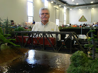
Here is an early morning shot showing John behind the module. That is a very slow moving train as it took all night to get across that bridge. John is a great guy, an excellent modeller and has more hair than I do. John also uses a really great method for legs. He utilizes plastic pipe which I will try to emulate since my legs take the longest in set up and take down.
The next two shots are of the farmer's field, harvesting hay. I love that wooden split rail fence. Jim Martin's famous back is in the second shot.


The next part of the modules is the bridge crossing the the country road. There is a cute little stream alongside.


As per usual, the 3 musketeers, Jim., Pete and myself were there. I guess we can call John our d'Artangan. The show was held in the Field Room of Carlton U. The floor was kind of spongy which saved our knees, backs and feet.
Paul Raham and Simon Parent came up on Saturday and helped to run the trains. Simon showed off his excellent locomotives, including the now famous GT USRA 0-6-0. You were missed on Sunday, Paul and Simon.
I am not sure about the numbers but the show seemed to be well attended. I was impressed with the crowds as they crowded around our set up. We did not use our stanchions but I still think they are necessary.
Alex Binkley was there as well building an Altoona Works Canadian Grain Elevator. Greg Shrubsole showed me a thermal plastic casting procedure that can work in your oven (not mine) at 350 degrees.
Jim, it was great travelling with you and I hope that I didn't bore you with my stories. The renting of the van was necessary.
I believe that we all had a great time and I am looking forward to Springfield, Oregon the home of Homer Simpson. Just kidding...Springfield, Mass in 2013.
cheers, eh?
Before we got to the show, we went to Paul Raham's for lunch and a small operating session. Paul models 1910 era in southern Ontario in S scale. It is a wonderful S scale layout and I got to run a very nice CPR consolidation that Paul had built from an Omnicon. I saw Paul's helix in action and now I am rethinking my layout design.
The following are shots of John Johnston's modules.


Here is an early morning shot showing John behind the module. That is a very slow moving train as it took all night to get across that bridge. John is a great guy, an excellent modeller and has more hair than I do. John also uses a really great method for legs. He utilizes plastic pipe which I will try to emulate since my legs take the longest in set up and take down.
The next two shots are of the farmer's field, harvesting hay. I love that wooden split rail fence. Jim Martin's famous back is in the second shot.


The next part of the modules is the bridge crossing the the country road. There is a cute little stream alongside.


As per usual, the 3 musketeers, Jim., Pete and myself were there. I guess we can call John our d'Artangan. The show was held in the Field Room of Carlton U. The floor was kind of spongy which saved our knees, backs and feet.
Paul Raham and Simon Parent came up on Saturday and helped to run the trains. Simon showed off his excellent locomotives, including the now famous GT USRA 0-6-0. You were missed on Sunday, Paul and Simon.
I am not sure about the numbers but the show seemed to be well attended. I was impressed with the crowds as they crowded around our set up. We did not use our stanchions but I still think they are necessary.
Alex Binkley was there as well building an Altoona Works Canadian Grain Elevator. Greg Shrubsole showed me a thermal plastic casting procedure that can work in your oven (not mine) at 350 degrees.
Jim, it was great travelling with you and I hope that I didn't bore you with my stories. The renting of the van was necessary.
I believe that we all had a great time and I am looking forward to Springfield, Oregon the home of Homer Simpson. Just kidding...Springfield, Mass in 2013.
cheers, eh?
May 4, 2012
River Raisin USRA GT 0-6-0 part 2
I have completed my customization of the RR model. Here is the final result and a quick explanation of the modifications I did.

One of the difference from the RR model and specifically to road number 7529. Engine 7529 had no safety panels behind the foot board. I wasn't planning on taking them out because I thought they were cast in. After a close examination, I noticed they were add-on and decided to unsolder them. Since I was going to repaint the pilot, I then decided to add the missing poling pockets and improved the look of the coupler pocket using styrene tubing and pieces.

Another small detail that was missing is the electrical box on the front cab wall. I used one of my own castings and fix it with ACC.

Now back to my original plans:
Wipers for Electrical pick-up and the Cam on the Locomotive:
I
replaced the 3 small bearing cover plates on the left (insulated side) with a
long piece of 1/32” double sided PC board. On the side up (bearing
side), I solder a 0.018” thick piece to match the cover plate. On the
down side (towards the tracks), I have first drilled the holes for the mounting
screws and made insulation cuts in the copper to insulate the mounting
screws. Then I made the wipers from 0.005”phosphor bronze flat sheet and solder in
place. I have solder and run a small piece of wire to connect all
three wipers up to the decoder on top of the motor.
For
the cam wiper, I used the brake rigs details as holder. Again, using
the 1/32” double sided PC board, I solder on side on the brake rig, behind the
cam and solder a piece of phosphor bronze on the other side.

Decoder
installation:
At
first, I was going to install the Tsunami decoder (TSU-1000) in the tender.
After test fitting, I realized that I could fit it on top of the motor in
the boiler. Installing the decoder inside the locomotive is my favorite
option for many reasons, for one, less wires between the locomotive and the
tender, especially if you use the mechanical cam trigger and able to fit the
speaker inside the boiler, since I also build or modify all my locomotives for all
wheel pick up, it allows the engine to run by itself without the tender
attached. Not that I run my locomotives without a tender but it makes it
easier during programming or test run. Another advantage as well is to
have as much as possible the wiring on the frame/mechanism and have connectors
for the lights and speaker when taking off the boiler.

Boiler Modification:
 I
made 2 minor modifications on the boiler assembly. The first one was to
allow a close coupling of the tender and make an opening below the cab floor to
run the wire harness. To do this, I have unsolder the bumper
casting. This is not a detail than can be seen and additionally, it was
oversize, probably to fill the larger than scale opening between the tender and
locomotive. Then using a cut off tool and some filling, I made an opening
between the 2 screw holes, large enough so that a bundle of several wires can
go through.
I
made 2 minor modifications on the boiler assembly. The first one was to
allow a close coupling of the tender and make an opening below the cab floor to
run the wire harness. To do this, I have unsolder the bumper
casting. This is not a detail than can be seen and additionally, it was
oversize, probably to fill the larger than scale opening between the tender and
locomotive. Then using a cut off tool and some filling, I made an opening
between the 2 screw holes, large enough so that a bundle of several wires can
go through.
The
second one was to open up for about 3/8” longer the wide opening of the
boiler. This was require to be capable of fitting the boiler on top of
the frame with the Tsunami decoder wrapped on top of the motor. Again,
this is not a visible modification, the larger opening remains behind boiler
mounted details.

Speaker
installation:
The
speaker with enclosure is mounted loose inside the smoke box section of
the boiler, replacing the weight. Before doing this, I tested the pulling
power of the locomotive without the weight. It could still pull a 12-car string
of full length AM Pullman cars. That’s good enough for me….. The
speaker must be installed after the boiler is assembled over the chassis,
through the smoke box front.

Here is the smoke box front where I replaced the number board with the correct CN style.

Tender modification:
 Then
I have added the wipers on the insulated wheels. That was not an easy job
because the retaining chain details had to be detached and it was not easy to
put them back in place. I have installed the wiper by using my own
etch wiper holders and phosphor bronze wire. I used the existing mounting
screw mount of the truck assembly but replaced with a nylon screw for
insulation. I forgot to take a picture of that before putting back the
truck in place and will not take them out again because of the tedious chain
installation.
Then
I have added the wipers on the insulated wheels. That was not an easy job
because the retaining chain details had to be detached and it was not easy to
put them back in place. I have installed the wiper by using my own
etch wiper holders and phosphor bronze wire. I used the existing mounting
screw mount of the truck assembly but replaced with a nylon screw for
insulation. I forgot to take a picture of that before putting back the
truck in place and will not take them out again because of the tedious chain
installation.
I
have oversee one thing though, I did not revert the insulated side on the
tender. This means that the tender and boiler are not the same
polarity. This is not an issue so to speak but with a close coupling,
there is always a risk of having the locomotive and tender touching in sharp
curves and it might create a short. It is not a problem on my home
layout but it could on someone else or sharp sidings the workshop
modules. If I see that it become a problem, I will make the change but it
means disconnecting the chains again L
Below are additional photos of the finished model.


May 2, 2012
River Raisin USRA GT 0-6-0
Just wanted to let everyone know that I started to customize this little gem. I will hopefully post some photos before end of the week.
Here is what I have done so far:
- Added wipers for all wheel pick up.
- Installed a Tsunami decoder in the locomotive with a medium oval speaker in the boiler. This is important to me. Chuff sound coming off the tender doesn't sound right!
- Shorten the coupling spacing distance between the locomotive and tender almost to scale. In theory, it should still negotiate a 32" radius but on my layout, the minimum is 50" and I use #8 switches, no problem at all. Not sure if it will work Ok on a #6 switch or shorter radius.
- Installed a cam wiper for synchronized chuff
- Replaced the Kadee couplers with the Walter HO couplers. This is not final. I want to evaluate this cheap oversize HO coupler for look and operation. If I don't like, I'll install the SHS coupler instead.
Next step is to replace the number board with one of my own casting. This is about the only flaw in this locomotive (IMO) to the prototype that is worth mentioning. I will also replace the incandescent lights with LEDs and my own lens in the tender and engine headlights. Of course it won't look as new and will weather it to my taste.
I should be able to finish most of my modifications before Ottawa train show this Saturday. (maybe just the weathering portion won't be done). I plan to bring it so that she could take some switching assignment on the S Scale Workshop modules.
Subscribe to:
Posts (Atom)